
Span-Based Concept-Design Guidance for Low-Carbon Reinforced Concrete Floor Systems: A Synthesis of Slab Typology and Beam Configuration Chia Paknahad∗1, Mosleh Tohidi2 1Department of Civil Engineering and Built Environment, School of Computing and Engineering, University of West London, London W5 5RF, UK; chia.paknahad@uwl.ac.uk 1 Department of Civil Engineering and Built Environment, Croydon University Centre, Croydon, London, UK; mosleh.tohidi@croydon.ac.uk (Received keep as blank , Revised keep as blank , Accepted keep as blank ) |
|---|
|
1. Introduction
The environmental and economic performance of reinforced concrete (RC) buildings is strongly influenced by decisions made during the earliest stages of structural design. Among these decisions, the selection of the floor system is particularly important because it directly affects material consumption, structural weight, construction requirements, and overall project cost. Chastas et al. [1] and Dunant et al. [2] demonstrated that a substantial proportion of a building’s embodied carbon is effectively determined during the conceptual design stage, before detailed structural analysis and optimisation are undertaken. This issue is especially critical for RC buildings, where concrete and reinforcing steel constitute the majority of structural mass and associated greenhouse gas emissions, as reported by Fishman et al. [3] and Marinova et al. [4]. Consequently, floor system selection should be regarded not only as a structural design choice but also as a key determinant of building sustainability and economic performance.
The significance of this decision is closely linked to the environmental burden associated with cement and steel production. Miller et al. [5] and Andrew [6] reported that cement manufacturing accounts for approximately 7–8% of global carbon dioxide emissions, largely due to the extensive worldwide use of concrete. Reinforcing steel production contributes a further share, with Cullen et al. [7] estimating that steel manufacturing is responsible for approximately 1.5% of global CO2 emissions. As operational energy demands continue to decline through improvements in building envelopes, energy systems, and grid decarbonisation, embodied carbon has emerged as a dominant component of whole-life environmental impact, as highlighted by Pomponi and Moncaster [8]. This transition is reflected in industry roadmaps, including the Global Cement and Concrete Association (GCCA) roadmap, which identifies design efficiency and intelligent structural solutions as major contributors to achieving net-zero concrete by 2050 [9].
Within RC buildings, floor systems represent one of the most effective opportunities for reducing embodied carbon and construction cost. Hart et al. [10], Hafez et al. [11], and Helal et al. [12] reported that suspended floor systems commonly account for approximately 60% of the total concrete volume used in multi-storey buildings, so even modest improvements in floor efficiency can produce substantial reductions at the building scale. Röck et al. [13] and Chastas et al. [1] observed that the embodied carbon intensity of concrete-framed buildings varies considerably, ranging from approximately 400 to 1200 kgCO2e/m2 depending on structural layout, span length, and floor typology. More ambitious low-carbon benchmarks proposed by Pasanen and Castro [14] and Arceo et al. [15] suggest target values between 137 and 367 kgCO2e/m2. Among the design parameters influencing embodied carbon, floor geometry, structural typology, and span arrangement are consistently identified as the most influential factors, because floor systems contain more than half of the total concrete volume within a building [16]. Although optimisation through higher-strength materials and advanced analysis methods can further improve performance [17], their impact is generally secondary compared with the selection of an efficient structural system.
Despite the growing importance of embodied carbon reduction, existing research remains fragmented. Numerous studies have focused exclusively on flat slab systems due to their simplicity and widespread adoption; for example, Trinh et al. [18] and Kanavaris et al. [19] investigated embodied carbon optimisation in flat slab structures. However, alternative floor systems such as ribbed and waffle slabs have repeatedly demonstrated significant reductions in embodied carbon relative to conventional flat slabs [11,16]. Belizario-Silva and França [20] showed that strategically positioned beams can achieve substantial carbon savings, while Whiteley et al. [21] demonstrated the efficiency gains achievable through optimisation of reinforced concrete floor grillages. Nevertheless, studies comparing slab typologies rarely investigate the influence of internal-beam arrangements, whereas studies focusing on beam optimisation are typically restricted to a single floor typology. As a result, the two fundamental design questions faced by engineers during conceptual design, namely which floor system should be selected and how that system should be configured, are usually addressed independently. De Wolf et al. [22] further noted the lack of integrated frameworks capable of assessing embodied carbon and economic performance consistently across alternative structural systems. Consequently, designers seeking guidance during early-stage design must often rely on findings from separate studies that were not intended to be interpreted collectively.
To address aspects of this research gap, the authors have previously examined eco-friendly flooring systems for RC structures [23] and, in a comprehensive comparison, evaluated three RC floor systems, namely flat slabs, beam-and-slab systems, and two-way joist slabs, across span lengths ranging from 4 to 14 m and three concrete strength grades [24]. That study generated 324 Eurocode-compliant design alternatives and demonstrated that two-way joist slabs achieved embodied carbon reductions of approximately 25 to 35% and cost savings of approximately 20 to 35% compared with competing systems at spans exceeding 10 m. Subsequently, the influence of beam arrangement within two-way joist slabs was investigated by comparing four structural configurations [25]. Those results indicated that two-way joist without beams slabs provide the most efficient solution at short spans, whereas fully framed beam arrangements become increasingly advantageous as span lengths approach and exceed 10 m. While these studies provide valuable insights, each addresses only one aspect of the overall design problem: the former focuses on slab typology selection, whereas the latter concentrates on beam configuration within a single slab system.
In practice, conceptual structural design is fundamentally span-driven. Engineers are typically required to determine the most appropriate floor system for a given span and, where a two-way joist slab is selected, to identify the most suitable beam arrangement. Existing studies do not directly support this decision-making process because their findings are organised according to either floor typology or beam configuration rather than span requirements. The objective of the present study is therefore not to generate new analytical data but to synthesise and reorganise existing evidence into a unified, span-based design framework.
The findings reported in the two source studies [24,25] are reinterpreted according to three practical span categories: short spans (4–6 m), medium spans (8–10 m), and long spans (12–14 m). Based on this reorganisation, a hierarchical decision framework is proposed. The first stage identifies the most suitable floor typology for each span category; the second stage determines the optimum beam configuration when a two-way joist slab is selected. By transforming two independent datasets into a single span-based decision framework, the proposed methodology provides practical guidance for feasibility studies and conceptual design, where the majority of embodied carbon commitments are established. In doing so, the study supports the design-led decarbonisation strategies advocated by the GCCA roadmap [9] and the embodied carbon guidance published by the Institution of Structural Engineers [26].
It is important to distinguish the guidance proposed here from the tools already available to UK practitioners. The Concrete Centre's CONCEPT tool [33] and the associated Economic Concrete Frame Elements guidance provide span-to-depth charts, budget cost rates and, in recent releases, embodied carbon output for a scheme that the designer has already defined. The user must first select both the floor typology and the grid before any output is produced, and the depth guidance rests on span-to-depth rules rather than on case-by-case serviceability verification. Neither ranks alternative typologies against one another on a common carbon basis, and neither addresses the arrangement of beams within a ribbed or two-way joist floor. The Institution of Structural Engineers' guidance [26] standardises how embodied carbon should be quantified and reported, but it is deliberately system-agnostic and offers no selection guidance. Neither source therefore answers the two questions that arise first in concept design: which floor typology should be adopted for a given span, and how that system should then be configured. The specific contributions are:
A span-first synthesis that unifies two complementary Eurocode-compliant parametric studies, joining the typology decision and the beam-configuration decision into one continuous workflow ordered the way engineers think. It is this integration of the two decisions, each of which is well covered in isolation but neither of which is linked to the other in existing design tools, that constitutes the novel contribution.
A span-dependent design matrix that merges the 324 typology cases of the first study with the beam-configuration cases of the second under a single, consistent set of A1–A3 ICE v5.0 emission factors and cost rates.
A concept-stage decision aid for office floors spanning 4–14 m, framed in the terms an engineer uses before any detailed analysis is performed.
The paper re-analyses, re-normalises and re-organises the outputs of two previously published parametric studies [24,25] into a form that maps onto the sequence of decisions made at concept design. The contribution is therefore a validated design aid rather than a new analysis method, and it should be used as such: as a first-pass indication of the likely optimum, to be confirmed by scheme-specific design. The boundary conditions within which the guidance applies, and the factors it does not consider, are set out in Section 7.
2. Structure of the Design Guidance
The proposed guidance is organised as a two-level hierarchical decision process, applied across three span bands. The logic reflects the order in which structural engineers typically make floor-system decisions during concept design: first, the broad typology is chosen based on span, architectural constraints, and service integration requirements; second, within the chosen typology, detailed configuration choices are made to optimise structural and environmental performance. The overall structure of the decision framework is illustrated in Figure 1.
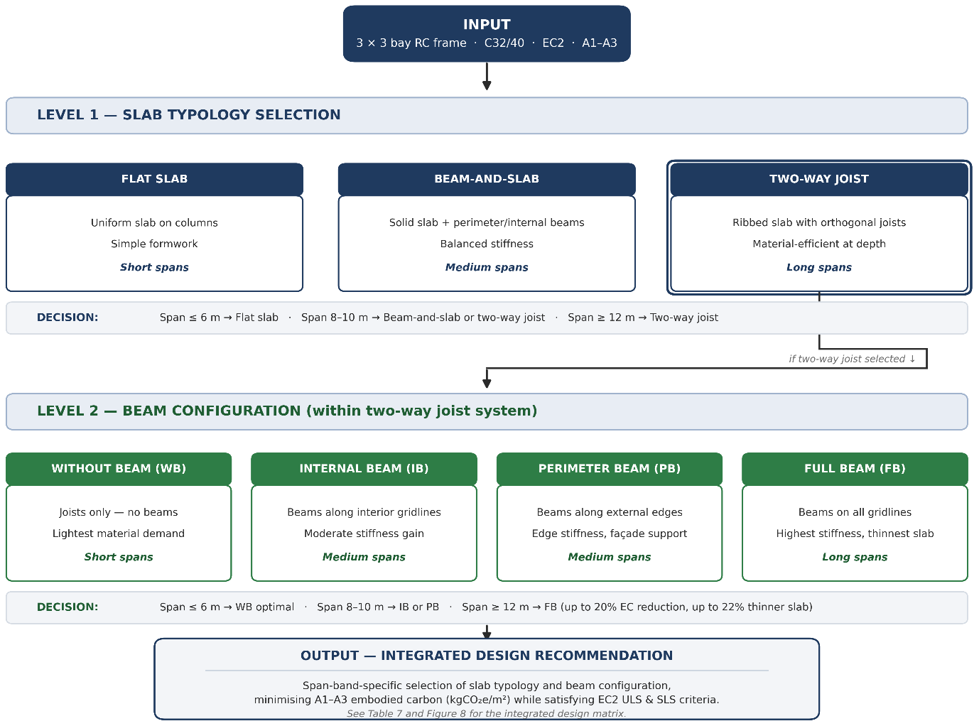
Fig. 1 Two-level hierarchical decision framework for low-carbon RC floor design, structured by span band.
2.1 Decision levels
Level 1 addresses slab typology selection. Three systems widely used in UK practice are compared: the flat slab, supported directly on columns; the beam-and-slab system, with two-way slabs supported on orthogonal monolithic beams; and the two-way joist slab, with a thin topping supported on orthogonal ribs. The exploded arrangement of the principal floor systems considered is shown in Figure 2, where the flat slab with drop panels is included as a variant of the flat slab system.
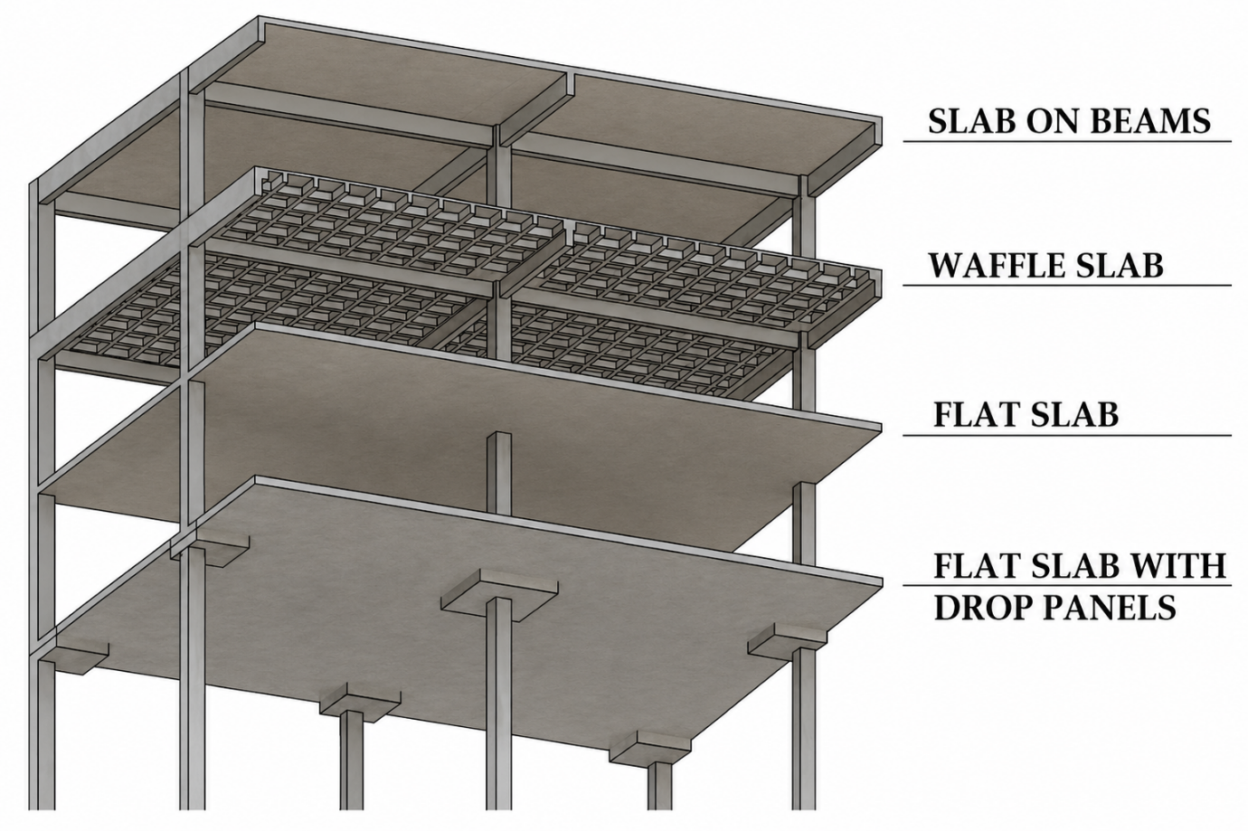
Fig. 2 Exploded view of the reinforced concrete floor systems considered at Level 1: slab on beams (beam-and-slab), two-way joist, flat slab, and flat slab with drop panels.
Level 2 addresses beam configuration within the two-way joist system. Four configurations are considered: without beam, where the slab is supported directly on columns through ribs and drop panels; internal-beam, with beams on internal grid lines only; perimeter-beam, with beams on the outer edge only; and full-beam, with a continuous beam grillage along every column line in both directions. Three-dimensional views of the four configurations are shown in Figure 3.
(a) without beam |
(b) internal-beam |
|---|---|
(c) perimeter-beam |
(d) full-beam |
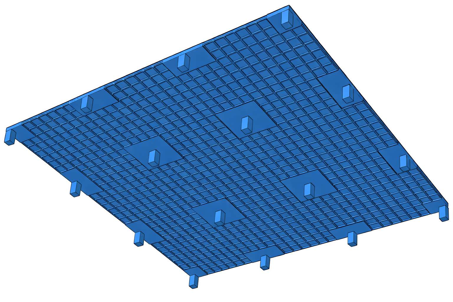
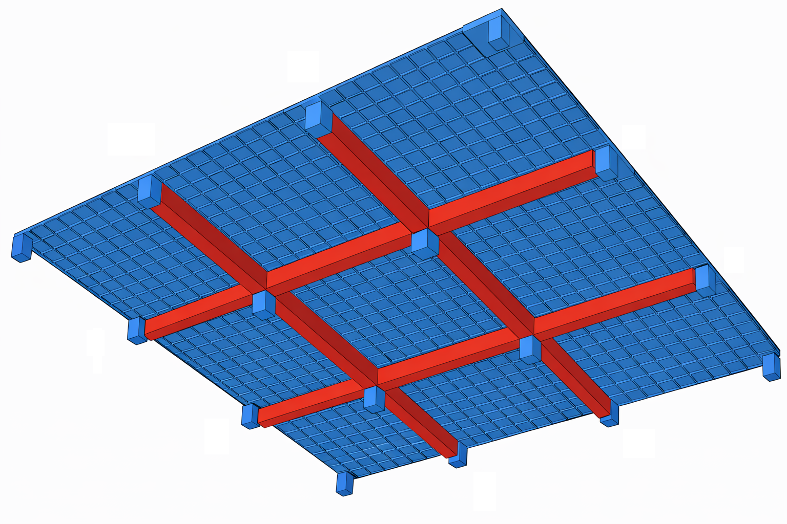
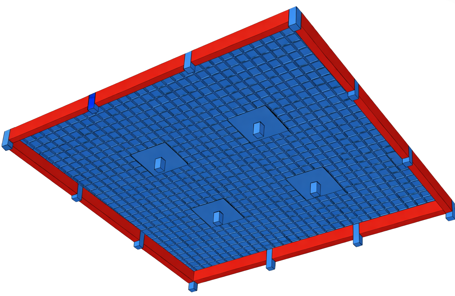
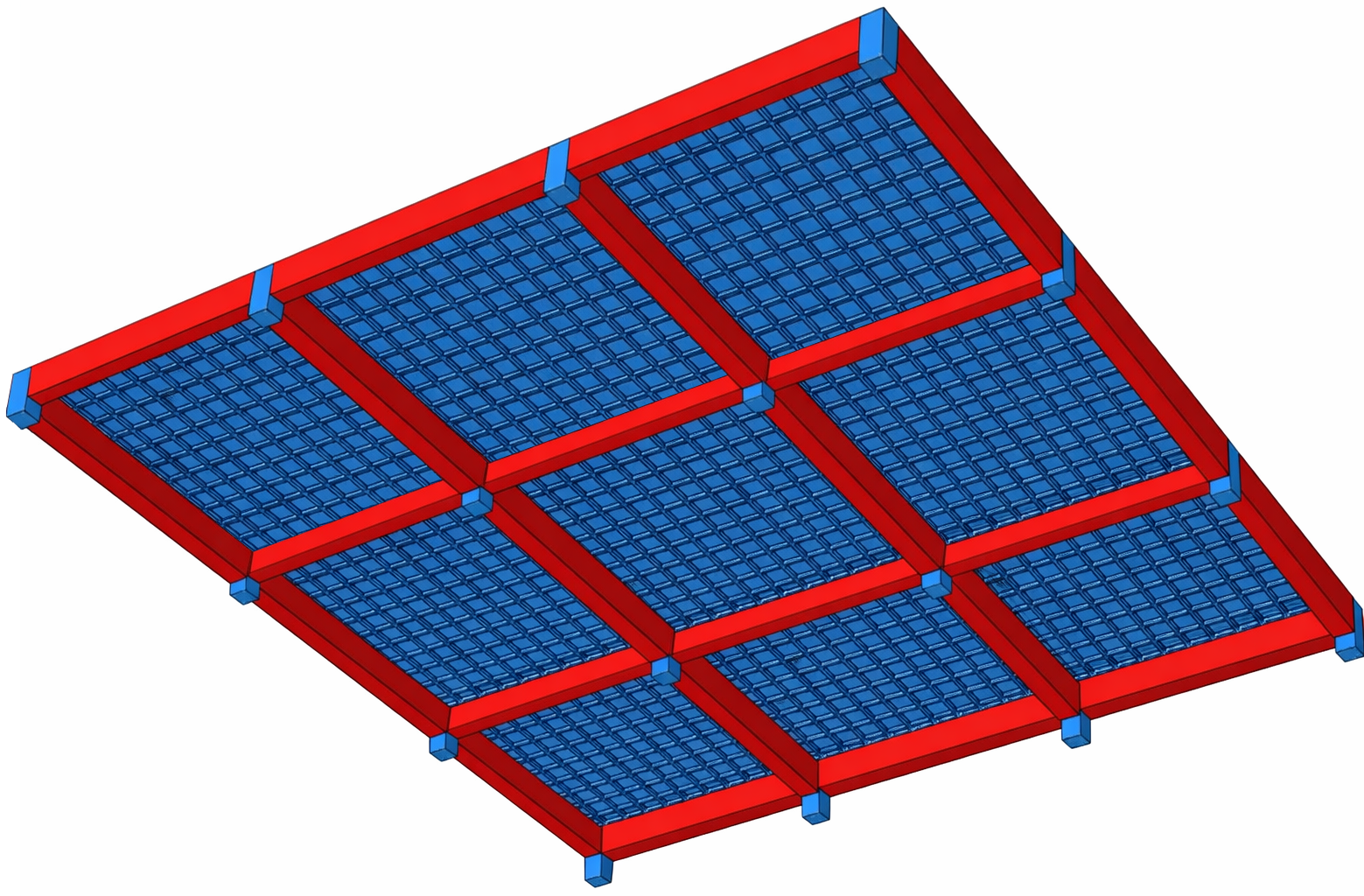
Fig. 3 Three-dimensional views of the four beam configurations considered at Level 2 within two-way joist slab systems: (a) without beam, (b) internal-beam, (c) perimeter-beam, (d) full-beam.
2.2 Span bands
Rather than reporting results for every individual span combination, the framework aggregates outcomes into three span bands that align with the natural crossover points identified in the source studies:
Short span (4–6 m): typical of small cellular office layouts, residential applications, and short-span commercial zones.
Medium span (8–10 m): typical of standard office bays, where competing design considerations (flat slab simplicity against joist efficiency) produce a transition zone.
Long span (12–14 m): typical of open-plan offices, column-free zones, and applications requiring architectural flexibility.
These bands correspond to the span regions in which design behaviour, governing criteria, and the ranking of alternatives change qualitatively. The crossover at approximately 8 m marks the point at which flat slabs lose efficiency against two-way joist systems, while the crossover at approximately 10 m within the joist family marks the transition from without-beam to full-beam optimality.
2.3 Scope and boundary conditions
The guidance applies to the scope defined by the two source studies: a regular 3 × 3 bay RC frame with a storey height of 3.0 m, designed in accordance with Eurocode 2 [29] for office occupancy. C32/40 concrete and B500C reinforcement are adopted as the baseline material specification at Level 2, whereas the Level 1 results reported in Section 4 are presented at C25/30, with C32/40 and C40/50 also examined. Values drawn from the two levels are therefore reported at different concrete grades and are not directly comparable in absolute terms. The grade is stated in every figure caption and table footnote, and each level is internally consistent, so the ranking of alternatives within each level is unaffected. Embodied carbon is assessed for life-cycle modules A1–A3 in accordance with EN 15804 [31] using emission factors from the Institution of Structural Engineers guidance [26] derived from the ICE v5.0 database [32]. Construction cost is estimated using unit rates from the Concrete Centre CONCEPT tool [33].
3. Methodology
A structured parametric modelling and optimisation workflow was developed to evaluate and compare RC floor systems on a span-by-span basis, comprising six stages: structural modelling, Eurocode-based design, nonlinear finite-element simulation, material quantification, embodied carbon and cost calculation, and span-band synthesis. The assessment focuses on structural concrete and reinforcing steel, which together account for around 80% of total material intensity and 90% of overall embodied carbon in typical multi-storey buildings; non-structural elements were excluded, in line with both source studies.
3.1 Structural configuration
Both source studies adopted a 3 × 3 bay RC frame (4 × 4 column grid) with bay spans varied from 4 m to 14 m in 2 m increments in both orthogonal directions, and a constant 3.0 m floor-to-floor height. Column cross-sections were scaled from 400 × 400 mm for short spans to 600 × 600 mm for long spans. For each bay-span combination in the first study, the design was performed at three concrete grades (C25/30, C32/40, and C40/50), generating 324 Eurocode-compliant design alternatives. In the second study, the analysis was fixed at C32/40 to isolate beam-layout effects. Slab thickness, rib geometry, and beam dimensions were adjusted iteratively within practical design limits to satisfy Eurocode strength and serviceability requirements; member size ranges across the parametric grid are summarised in Table 1.
Table 1 Representative member sizes by span band, consolidated from the two source studies.
| Span band | System | Lx × Ly (m) | Grade | Slab (mm) | Rib (mm) | Beam b×h (mm) | Column (mm) |
|---|---|---|---|---|---|---|---|
| Short | Flat slab | 4 × 4 | C25/30 | 180 | – | – | 400×400 |
| Short | Beam-and-slab | 4 × 4 | C25/30 | 120 | – | 200×400 | 400×400 |
| Short | Two-way joist | 4 × 4 | C25/30 | 50 | 100 | – | 400×400 |
| Medium | Flat slab | 8 × 8 | C25/30 | 200 | – | – | 500×500 |
| Medium | Beam-and-slab | 8 × 8 | C25/30 | 260 | – | 400×500 | 500×500 |
| Medium | Two-way joist | 8 × 8 | C25/30 | 100 | 100 | – | 500×500 |
| Long | Flat slab | 12 × 12 | C25/30 | 450 | – | – | 600×600 |
| Long | Beam-and-slab | 12 × 12 | C25/30 | 490 | – | 600×700 | 600×600 |
| Long | Two-way joist | 12 × 12 | C25/30 | 100 | 140 | – | 600×600 |
3.2 Design approach
All alternatives were designed using CSI ETABS v22 [34] and CSI SAFE v22 [35]. These programs were selected for their ability to perform integrated RC slab design, deflection checks, and reinforcement detailing in compliance with Eurocode 2 [29] and are widely used in UK structural engineering practice. A two-stage modelling workflow was applied to both parametric streams: global linear elastic frame analysis in ETABS to capture stiffness and load transfer, followed by slab-level nonlinear cracked-section analysis in SAFE to evaluate flexural response, cracking, and long-term deflection. Both Ultimate Limit State (ULS) and Serviceability Limit State (SLS) criteria were verified in accordance with EN 1992-1-1 [29], including flexural and shear strength, punching shear at column heads, crack width control, and long-term deflection limited to span/250 using the Age-Adjusted Effective Modulus method. All designs also satisfied the R90 fire resistance requirements of EN 1992-1-2 [30]. A mesh sensitivity study with element sizes between 2.0 m and 0.05 m was conducted; results stabilised at 0.5 × 0.5 m, which was adopted for all analyses. The material properties common to both streams are listed in Table 2.
Table 2 Material properties used in structural design.
| Property | Value | Unit |
|---|---|---|
| Clear cover | 15 | mm |
| Density of concrete | 2548 | kg/m³ |
| Density of steel | 7850 | kg/m³ |
| E (C25/30) | 31000 | MPa |
| E (C32/40) | 33350 | MPa |
| E (C40/50) | 35000 | MPa |
| E (steel) | 200000 | MPa |
| fy (reinforcement) | 500 | MPa |
| Poisson’s ratio (concrete) | 0.2 | – |
| Poisson’s ratio (steel) | 0.3 | – |
3.3 Embodied carbon assessment
The system boundary was restricted to life-cycle modules A1–A3 (product stage) in accordance with EN 15804 [31], using emission factors recommended by the Institution of Structural Engineers [26] and derived from the ICE Database v5.0 [32]. This scope captures the dominant share of embodied carbon in RC structures and enables consistent comparison between alternatives at the early design stage. The embodied carbon intensity per unit floor area was computed as shown in Equation (1), where Qi is the quantity of material i, ECCi is its embodied carbon coefficient, and A is the floor area.
| EC (kgCO2e/m2$) = \sum_{}^{}\frac{\left( Q_{i} \times {ECC}_{i} \right)}{A}$ | (1) |
|---|
Table 3 Embodied carbon factors for UK in-situ concrete and reinforcement [26,32].
| Material | EC Ratio | Unit |
|---|---|---|
| Concrete C25/30 | 0.100 | kgCO2e/kg |
| Concrete C32/40 | 0.120 | kgCO2e/kg |
| Concrete C40/50 | 0.138 | kgCO2e/kg |
| Reinforcement B500C | 0.760 | kgCO2e/kg |
3.4 Cost assessment
Material costs were derived from the CONCEPT tool of the Concrete Centre [33], using UK average rates that include supply and placement (Table 4). All costs are reported in £/m2, computed as shown in Equation (2), where Qi is the quantity of material i, URi is its unit rate, and A is the floor area.
| $$Cost\ (\pounds/m^{2}) = \sum_{}^{}\frac{\left( Q_{i} \times {UR}_{i} \right)}{A}$$ | (2) |
|---|
Table 4 Material unit costs for UK in-situ concrete and reinforcement [33].
| Material | Cost | Unit |
|---|---|---|
| Concrete C25/30 | 130 | £/m³ |
| Concrete C32/40 | 145 | £/m³ |
| Concrete C40/50 | 160 | £/m³ |
| Reinforcement B500C | 980 | £/tonne |
3.5 Loading
Loads were applied in accordance with EN 1990 [27] and EN 1991-1-1 [28]: a superimposed dead load of 2.0 kN/m2 and an imposed live load of 2.5 kN/m2, representing typical office occupancy. Ultimate load combinations used partial safety factors of 1.35 for permanent actions and 1.50 for variable actions. Long-term deflection was evaluated using a four-case nonlinear loading protocol incorporating immediate, sustained, and time-dependent effects under cracked-section conditions, as shown in Table 5. The final long-term deflection is calculated by combining these cases, as shown in Equation (3), with the result checked against the span/250 limit.
Table 5 Four-case nonlinear loading protocol for long-term deflection assessment.
| Case ID | Load Case Description | Applied Loads | Analysis Type |
|---|---|---|---|
| Case 1 | Immediate Dead Load | DL | Nonlinear (Cracked) |
| Case 2 | Immediate All Load | DL + SD + LL | Nonlinear (Cracked) |
| Case 3 | Immediate Sustained Load | DL + SD + αLL | Nonlinear (Cracked) |
| Case 4 | Long-Term Sustained Load | DL + SD + αLL | Nonlinear (Long-Term Cracked) |
Note: DL = Dead Load; SD = Superimposed Dead Load; LL = Live Load; α = quasi-permanent factor for the imposed load (0.3 for office occupancy).
Long-Term Deflection = Case 4 + (Case 2 − Case 3) − Case 1 (3)
4. Level 1 — Slab Typology Selection
Three slab systems (flat slab, beam-and-slab, and two-way joist) are compared in terms of embodied carbon and cost across short, medium, and long spans. The overall variation of embodied carbon and cost with span across the three systems is shown in Figure 4, which provides the basis for the span-band interpretation that follows.
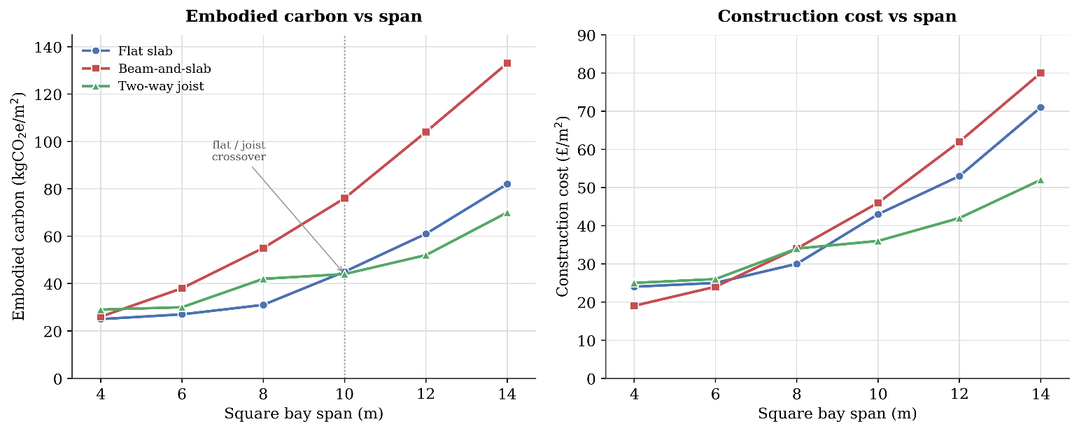
Fig. 4 Embodied carbon and cost intensity versus span length for the three slab systems at grade C25/30.
4.1 Short-span behaviour (4–6 m)
For short spans, all three systems perform competitively, with embodied carbon in the range of about 25 to 38 kgCO2e/m2 and cost between about £19 and £26/m2. The flat slab is the most carbon-efficient option in this band: for a 4 × 4 m bay at C25/30 it recorded approximately 25 kgCO2e/m2 at £24/m2, rising only to about 27 kgCO2e/m2 and £25/m2 at 6 × 6 m. The beam-and-slab system is competitive at 4 m (around 26 kgCO2e/m2) and is in fact the cheapest option at the shortest spans (£19/m2 at 4 × 4 m), but its material demand grows the most rapidly with span, reaching 38 kgCO2e/m2 by 6 × 6 m. The two-way joist slab is marginally higher in carbon (around 29 to 30 kgCO2e/m2) and the most expensive in this band (£25 to £26/m2), owing to minimum rib geometry and topping requirements that are not yet offset by structural demand. Differences between concrete grades at short spans are modest, because slab thickness is governed by minimum-cover, punching-shear, and durability requirements rather than flexural capacity, so the higher cement intensity of stronger mixes is not offset by section reductions. Within the short-span band the flat slab therefore represents the most practical choice for most applications, combining the lowest embodied carbon, near-lowest cost, and construction simplicity. The beam-and-slab system becomes attractive only where its marginal cost advantage, stiffness, or vibration performance justifies the additional beam elements. This behaviour is illustrated in Figure 5.
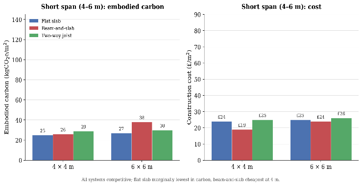
Fig. 5 Embodied carbon and construction cost of the three slab systems at short-span square bays, C25/30.
4.2 Medium-span behaviour (8–10 m)
The medium-span band is a transition zone in which the relative performance of the three systems changes. At an 8 × 8 m bay, the flat slab remains efficient (around 31 kgCO2e/m2 at £30/m2) and still outperforms the two-way joist (around 42 kgCO2e/m2 at £34/m2), but its embodied carbon then rises more steeply with span, driven by the increased slab thickness and punching-shear reinforcement required at slab-column connections. Beam-and-slab systems perform least well in this range, their combined concrete and reinforcement demand growing rapidly from 55 kgCO2e/m2 at 8 × 8 m to 76 kgCO2e/m2 at 10 × 10 m. Two-way joist slabs become increasingly efficient as span extends toward 10 m, where the ribbed geometry reduces concrete volume while maintaining adequate stiffness. By approximately 10 m the joist and flat slab curves cross: at 10 × 10 m the flat slab reaches about 45 kgCO2e/m2 while the joist holds at about 44 kgCO2e/m2, The joist also becomes the cheaper option at this point, at £36/m2 against £43/m2. Beyond 10 m the two-way joist is consistently lower on both metrics. The effect of grade also begins to bifurcate: for flat and beam-and-slab systems, raising the grade marginally reduces cost but increases embodied carbon, For the joist system, by contrast, higher grades start to show net benefits, because the ribbed geometry translates strength gains directly into reduced rib depth. For medium spans, the two-way joist system is generally the most efficient choice beyond the crossover, although flat slabs remain viable where architectural simplicity or programme constraints dominate. These trends are shown in Figure 6.
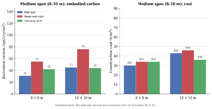
Fig. 6 Embodied carbon and construction cost of the three slab systems at medium-span square bays, C25/30.
4.3 Long-span behaviour (12–14 m)
Long spans reveal the greatest differentiation between systems. Beam-and-slab systems perform worst, with embodied carbon rising to approximately 133 kgCO2e/m2 and cost to £80/m2 at 14 × 14 m, due to the compounding material demand of both deep slabs and large beams. Flat slab embodied carbon also rises sharply, reaching approximately 82 kgCO2e/m2 at 14 × 14 m at a cost of about £71/m2, driven by the thickness increases required to control punching shear and long-term deflection. The two-way joist system consistently outperforms both alternatives: at 12 × 12 m it achieved approximately 52 kgCO2e/m2 and £42/m2, and at 14 × 14 m approximately 70 kgCO2e/m2 and £52/m2. Relative to the competing systems at 14 × 14 m square bays, this corresponds to a reduction of approximately 15% against the flat slab and approximately 50% against the beam-and-slab system, an average of approximately 32% across the two, with cost savings of approximately 20 to 35%. These margins apply within the scope of this study, namely square bays in a regular 3 × 3 bay office frame, and should not be extrapolated to irregular grids, non-square bays, or occupancies with substantially different imposed loading. Higher-strength concrete becomes increasingly beneficial in this band: because the ribbed geometry translates strength gains directly into reduced rib depth, raising the grade reduces both carbon and cost, the only typology for which this holds. The efficiency derives from the ribbed geometry, which achieves favourable stiffness-to-weight performance and limits concrete volume even as span increases. This differentiation is presented in Figure 7.
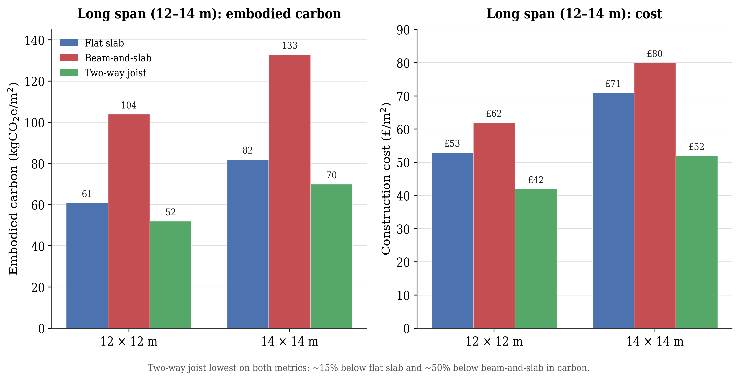
Fig. 7 Embodied carbon and construction cost of the three slab systems at long-span square bays, C25/30.
5. Level 2 — Beam Configuration Within Two-Way Joist Systems
To examine the influence of beam arrangement on the performance of two-way joist slabs, four beam configurations were evaluated at a fixed concrete grade of C32/40: without beam, internal-beam, perimeter-beam, and full-beam. The comparison of interest at this level is the relative performance of the four beam configurations, which is internally consistent within the source study. The variation of embodied carbon with span for each configuration is presented in Figure 8, which forms the basis for the span-band interpretation discussed in the following sections.
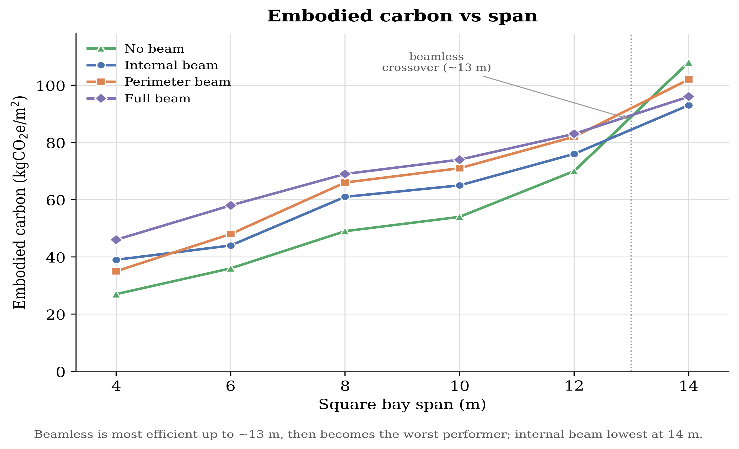
Fig. 8 Embodied carbon versus span for the four beam configurations of a two-way joist system across square bays, grade C32/40.
5.1 Short-span behaviour (4–6 m)
At short spans, adding beams to a two-way joist system offers no structural benefit. The slab panel is already efficient, and introducing beams simply adds concrete and reinforcement without reducing slab thickness or reinforcement demand. At 4 × 4 m, the without-beam configuration achieved approximately 27 kgCO2e/m2, whereas the beamed alternatives recorded between 35 and 46 kgCO2e/m2, an increase of roughly 30 to 70% with no corresponding performance gain. The penalty scales with the quantity of beam material introduced: the perimeter and internal configurations add least (35 and 39 kgCO2e/m2 at 4 × 4 m), while the full-beam grid adds most (46 kgCO2e/m2). The same ordering persists at 6 × 6 m, where the without-beam configuration remains lowest at approximately 36 kgCO2e/m2 and the full-beam configuration highest at 58 kgCO2e/m2. For short spans, the without-beam configuration is therefore unambiguously optimal, as shown in Figure 9. This is consistent with the Level 1 finding that flat slabs perform best in this range, since a two-way joist without beams behaves similarly to a flat slab with drop panels. The two levels are reported at different concrete grades, as noted in Section 2.3, so the agreement is one of ranking rather than of absolute value.
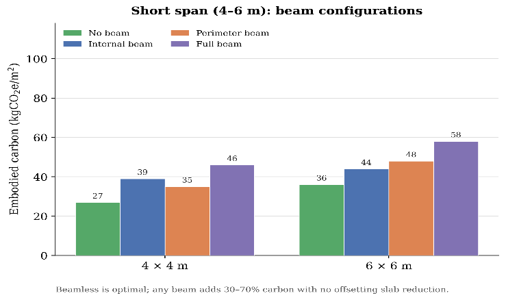
Fig. 9 Embodied carbon of the four beam configurations for a two-way joist system at short-span square bays, grade C32/40.
5.2 Medium-span behaviour (8–10 m)
Across the medium-span band the without-beam configuration remains the most efficient option, and the configurations have not yet crossed. At 8 × 8 m the without-beam layout recorded approximately 49 kgCO2e/m2, compared with about 61 kgCO2e/m2 for the internal-beam, 66 kgCO2e/m2 for the perimeter-beam, and 69 kgCO2e/m2 for the full-beam configuration. The ranking is preserved at 10 × 10 m (approximately 54, 65, 71, and 74 kgCO2e/m2 respectively), so each beamed configuration remains roughly 15 to 20 kgCO2e/m2 above the without-beam case throughout the band. The crossover at which beams begin to pay for themselves therefore lies beyond this band, in the long-span range. Among the beamed options, the internal-beam configuration is consistently the most efficient, since interior beams contribute to two-directional load redistribution, whereas the perimeter-beam configuration is consistently less efficient, for the reasons set out in Section 5.4. For medium spans, the without-beam configuration remains preferable on embodied carbon, although a beamed configuration may be justified where deflection control, vibration, or service integration governs the design. These trends are shown in Figure 10.
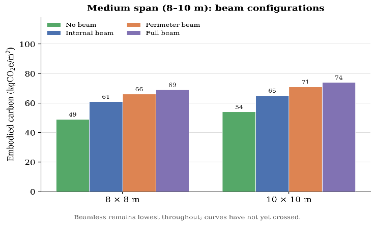
Fig. 10 Embodied carbon of the four beam configurations for a two-way joist system at medium-span square bays, grade C32/40.
5.3 Long-span behaviour (12–14 m)
The long-span band contains the crossover beyond which beams begin to pay for themselves. Up to 12 × 12 m the without-beam configuration is still the lowest-carbon option, at approximately 70 kgCO2e/m2 against 76, 82, and 83 kgCO2e/m2 for the internal, perimeter, and full-beam configurations respectively. As span extends to 14 m, however, serviceability constraints, particularly long-term deflection and punching shear, force a sharp increase in slab thickness in the without-beam layout. Its embodied carbon consequently rises steeply, to approximately 108 kgCO2e/m2. At that level the floor structure alone would account for a large fraction of the low-carbon whole-building benchmark discussed in Section 6.3. The beamed configurations, whose beams control slab deflection without requiring slab thickening, rise far more gradually. At 14 × 14 m the ranking inverts: the without-beam configuration becomes the worst performer, while the internal-beam (approximately 93 kgCO2e/m2) and full-beam (approximately 96 kgCO2e/m2) configurations are the most efficient, a reduction of roughly 11 to 14% relative to the without-beam case. The carbon crossover therefore occurs at approximately 13 m. The comparative embodied carbon of the four configurations at long span is shown in Figure 11.
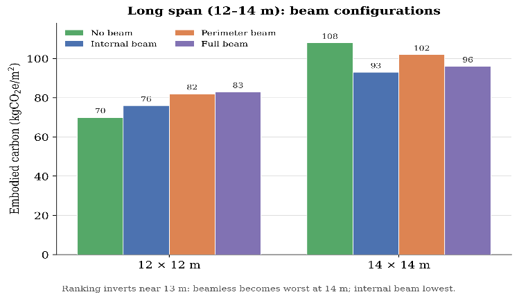
Fig. 11 Embodied carbon of the four beam configurations for a two-way joist system at long-span square bays, grade C32/40.
5.4 Why perimeter-only beam grids underperform
The perimeter-beam configuration is not optimal in any span band and becomes the worst of the beamed layouts at long span, recording approximately 102 kgCO2e/m2 at 14 × 14 m against 93 and 96 kgCO2e/m2 for the internal-beam and full-beam grids. The reason lies in where the governing demands sit within a two-way joist floor, and in which of them an edge beam is able to relieve.
In a two-way joist floor supported on a 4 × 4 column grid, three demands govern the section. The first is the mid-panel sagging moment and the associated long-term deflection of the interior panel, which sets the rib depth through the span/250 criterion. The second is the hogging moment and punching-shear demand at the four interior column heads, which sets the topping thickness and the extent of the solid drop panel. The third is the edge and corner condition, which is comparatively benign, since an edge column carries approximately half and a corner column approximately one quarter of the tributary area of an interior column, and the hogging moment at a discontinuous edge is smaller than at a continuous interior support.
A beam relieves the ribs only if it shortens their effective span or intercepts load before it reaches an interior column head. Perimeter-beams occupy the boundary grid lines and therefore do neither. The interior panels retain their full clear span in both directions, the interior column heads retain their full tributary load, and the mid-panel deflection that governs rib depth is essentially unchanged. Because rib depth and topping thickness are set by the most heavily loaded interior panel and are then applied uniformly across the floor for constructability, the governing section is unaltered by the presence of edge beams. The entire volume of perimeter-beam concrete and reinforcement is therefore added to the floor without permitting any compensating reduction elsewhere, and the configuration behaves as a near-pure material penalty across the whole span range.
Internal-beams behave differently. Placing beams on the interior grid lines subdivides the interior panels, reduces the clear rib span in both directions, and transfers a share of the panel load into the interior columns in bending rather than through punching. This reduces both the deflection-governed rib depth and the punching demand at the interior column heads, so the added beam material is at least partly recovered. The full-beam grid combines both effects and additionally provides continuous two-directional support to every panel, which is why the two converge at long span despite the full grid containing more material.
This mechanism also explains the ordering at short span, where the perimeter configuration records the lowest embodied carbon of the three beamed layouts, approximately 35 kgCO2e/m2 at 4 × 4 m against 39 and 46 kgCO2e/m2 for the internal-beam and full-beam grids. That position reflects only the small quantity of beam material introduced, not any structural efficiency. Measured against the without-beam case it remains a penalty of approximately 30%. As span increases, the material added by the perimeter-beams grows while the relief they provide remains negligible, so their relative position deteriorates steadily until they become the worst beamed option at 14 m. Edge beams remain justified where they are required for facade support, edge deflection control or torsional restraint, or where an upstand or downstand is architecturally required, but they should not be introduced as an embodied carbon reduction measure.
6. Integrated Design Guidance
6.1 Span-dependent design matrix
Combining the outcomes of Level 1 and Level 2 produces a unified, span-dependent design matrix, which is the principal output of this guidance and is intended for direct use at the concept-design stage. For each span band it states the recommended slab typology, the corresponding beam configuration within the two-way joist family, the appropriate concrete grade, and the expected embodied carbon and cost. The values are taken from the parametric results of the two source studies for the recommended system in each band, evaluated over square bays across the span band. As noted in Section 2.3, the Level 1 and Level 2 results are reported at different concrete grades, so the grade is stated against every value in Table 6.
The matrix is presented in Table 6. The same logic is presented in Figure 12 as a decision tree intended for direct use at the drawing board. The tree begins with an applicability gate: the conditions listed in Section 7.1 must all be satisfied before the guidance is used. It then resolves the Level 1 typology decision from the governing bay span, and the Level 2 beam-configuration decision from the additional criteria that apply within each band, including the embodied carbon crossover at approximately 13 m. The rule against perimeter-only beam grids and a summary of the boundary conditions are carried at the foot of the tree so that they remain visible whenever the figure is used in isolation.
Table 6 Span-dependent design matrix for low-carbon RC floor systems at concept stage.
| Span band | Governing span L (m) | Recommended typology | Beam configuration | Concrete grade | Embodied carbon (kgCO2e/m2) | Cost (£/m2) | Governing criterion |
|---|---|---|---|---|---|---|---|
| Short | 4–6 | Flat slab | – | C25/30 | 25–27 | 24–25 | Minimum thickness, cover and punching shear |
| Medium | 8–10 | Two-way joist | Without beam | C32/40 | 49-54 | 34–39 | Mid-panel long-term deflection (span/250) |
| Long, below crossover | 12–13 | Two-way joist | Without beam | C32/40 | 62–70 | 40–42 | Long-term deflection and interior punching shear |
| Long, above crossover | 13–14 | Two-way joist | Full beam grid | C32/40, C40/50 at 14 m | 93–96 | 46-51 | Long-term deflection (span/250) |
Embodied carbon covers modules A1 to A3 for the suspended floor structure only, comprising slab, ribs and beams. Short-band values are from the Level 1 typology study [24] at C25/30. Medium-band and long-band embodied carbon values are from the Level 2 beam-configuration study [25] at C32/40; the corresponding cost figures are derived from the same study using the unit rates in Table 4. Values are indicative concept-stage ranges for square bays under office loading. See Section 7 for boundary conditions.
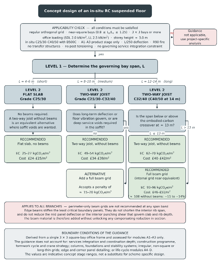
Fig. 12 Concept-stage decision tree for low-carbon RC floor system selection, combining the Level 1 typology decision and the Level 2 beam-configuration decision, with the applicability gate and boundary conditions within which the guidance holds.
The matrix shows a clear and consistent progression across the three bands. In the short-span band the flat slab, equivalent in performance to a two-way joist without beams, achieves the lowest values recorded across the parametric grid examined here, around 25 to 27 kgCO2e/m2 at a cost of approximately £24 to £25/m2, with the C25/30 grade entirely adequate. In the medium-span band the two-way joist without beams provides the best balance, with embodied carbon of approximately 49 to 54 kgCO2e/m2 at grade C32/40 and cost of approximately £34 to £39/m2. A full beam grid is introduced only as spans approach 10 m, where deflection or vibration criteria govern. This carries a carbon penalty of approximately 15 to 20 kgCO2e/m2, since the configurations do not cross on embodied carbon until approximately 13 m. In the long-span band the recommendation changes at the crossover. Up to approximately 13 m the without-beam configuration remains optimal at approximately 70 kgCO2e/m2. Beyond it, the full beam grid is recommended, recording approximately 96 kgCO2e/m2 at 14 × 14 m against 108 kgCO2e/m2 for the without-beam alternative. All long-span values remain substantially below those of the flat slab and beam-and-slab systems at the same spans.
6.2 Applying the guidance
The design decision proceeds as follows. First, the designer confirms that the floor plate satisfies the applicability conditions set out in Section 7.1, and identifies the governing span. For spans of 4 to 6 m, the flat slab is selected, being material-efficient, rapid to construct, and carbon-competitive; equivalently, a two-way joist without beams may be adopted where soffit voids are wanted for services. For spans of 8 to 10 m, the two-way joist without beams is selected, providing the best balance of carbon and cost in the transition zone, and may be adjusted toward a full-beam configuration as spans approach 10 m if deflection or vibration criteria become critical. For spans of 12 to approximately 13 m, the two-way joist without beams remains the selection, since it records approximately 70 kgCO2e/m2 against 83 kgCO2e/m2 for the full beam grid at 12 × 12 m. Beyond the crossover near 13 m the ranking inverts, and the two-way joist with a full beam grid is selected, delivering approximately 11% lower embodied carbon than the without-beam alternative at 14 m together with effective two-directional load sharing. The internal-beam grid records marginally lower embodied carbon at 14 m, approximately 93 against 96 kgCO2e/m2, and is a valid alternative where the full grid is not required for facade support or grid irregularity. Perimeter-only beam configurations are not recommended at any span band, for the reasons established in Section 5.4.
6.3 Relation to published low-carbon benchmarks
The values reported here must be interpreted against the correct system boundary. The results cover the A1 to A3 embodied carbon of the suspended floor structure alone, comprising concrete and reinforcement in the slab, ribs and beams, expressed per square metre of floor area. The low-carbon benchmarks proposed by Pasanen and Castro [14], at 137 to 367 kgCO2e/m2, and the product-stage values reported by Arceo et al. [15], cover the complete building, including the frame, substructure, envelope, finishes and, in some cases, services. A direct numerical comparison is therefore not meaningful.
A useful indication can nevertheless be obtained by considering the share the floor plate occupies within those totals. Suspended floors typically account for approximately 60% of the concrete volume in a reinforced concrete framed building [10,11,12], and the structural frame typically accounts for roughly half of the product-stage embodied carbon of a commercial building [13,19]. On that basis, a floor plate delivering 25 to 54 kgCO2e/m2 across the short and medium span bands leaves a scheme comfortably within reach of the lower part of the 137 to 367 kgCO2e/m2 band once columns, foundations, stability systems and non-structural elements are added. By contrast, the 82 and 133 kgCO2e/m2 recorded by the flat slab and beam-and-slab systems respectively at 14 × 14 m would commit a substantial fraction of the whole-building allowance to the floor structure alone, and would place a scheme towards or beyond the upper end of that band. The guidance therefore identifies the floor-system choices that keep a project within reach of the low-carbon benchmark. It does not, by itself, certify compliance with it.
The results are also conditioned by the C32/40 CEM I baseline adopted at Level 2 and the C25/30 to C40/50 range examined at Level 1. All alternatives share the same mix, so the ranking between systems is robust to the choice of binder, but the absolute values are not. Substituting 30 to 50% ground granulated blast-furnace slag, or a comparable proportion of fly ash, for Portland cement typically reduces the A1 to A3 carbon coefficient of a C32/40 mix by approximately 20 to 40%, and the use of recycled or secondary aggregates offers a further, smaller reduction. Because the concrete component dominates the totals reported here, such substitutions would scale all values downwards by a broadly similar proportion. They would not reverse the ranking between systems, but because the beamed configurations carry a higher reinforcement fraction than the ribbed alternatives, a lower concrete coefficient would slightly narrow their advantage at long span and could shift the crossover span. Quantifying that shift requires a re-run of the parametric grid with alternative binder specifications and is identified as future work in Section 7.3.
7. Limitations and Boundary Conditions
The guidance presented in Section 6 is derived from two parametric studies of a single building configuration. This section states the conditions under which it applies, the factors it does not represent, and its validation status.
7.1 Conditions under which the guidance applies
The guidance applies only within the following conditions. The floor plate must be a regular orthogonal grid of at least 3 × 3 bays, with near-square panels, taken here as a ratio between the two bay dimensions in the range 0.8 to 1.25, and with no transfer structures, irregular column offsets or large penetrations. Loading must be representative of office occupancy, with a superimposed dead load of 2.0 kN/m2 and an imposed load of 2.5 kN/m2. The storey height must be approximately 3.0 m, and the construction in-situ reinforced concrete of grade C25/30 to C40/50 with B500C reinforcement. Serviceability is assessed against a long-term deflection limit of span/250, and fire resistance against a requirement of R90. Post-tensioning, precast and hybrid systems are outside the scope, as is any scheme in which a service-integration or programme constraint governs the choice of floor system. Outside these conditions the ranking of alternatives may change, and scheme-specific analysis is required.
These conditions are also carried in Figure 12 as an applicability gate, so that they remain visible when the decision tree is used independently of the text.
7.2 What the guidance does not consider
Several factors that materially influence floor system selection in practice fall outside the scope of the underlying studies and are not represented in the guidance.
Services integration and coordination. The two-way joist soffit provides voids that can accommodate distribution within the structural depth, whereas a flat slab offers a flat soffit that simplifies suspended services but requires a separate service zone. The resulting difference in overall floor-to-floor height, and hence in facade area, column length and foundation load, is not captured. Where storey height is constrained, this consideration may reverse the recommendation given here.
Construction programme, formwork and temporary works. Flat slabs support rapid, repetitive table-form cycles, whereas two-way joist floors require moulds or proprietary formers and are typically slower per cycle. Programme duration, crane utilisation, preliminaries and site overheads are excluded from the cost model, which covers only material supply and placement. The cost comparisons therefore understate the position of the simpler typologies.
Scope of the structural assessment. Only the suspended floor is assessed. Columns, foundations, stability systems, cores and non-structural elements are excluded, although the self-weight reduction achieved by an efficient floor propagates into column and foundation sizing and would, if included, increase the advantage of the two-way joist at long span.
Life-cycle boundary. Only modules A1 to A3 are assessed. Modules A4 and A5 covering transport and construction, module B covering the use stage, and modules C and D covering end of life and beyond, are all excluded, as are reinforcement wastage, formwork carbon and the carbonation credit.
Geometry and occupancy. All results derive from square bays under office loading. Long-thin panels, single-span or two-bay layouts, edge and corner panel detailing, cantilevers, and residential, retail or industrial loading are not represented.
Material specification. A CEM I binder is assumed throughout. Low-carbon cements, supplementary cementitious materials and recycled aggregates are discussed in Section 6.3 but are not modelled.
Comparability between levels. The Level 1 and Level 2 results are reported at different concrete grades, as set out in Section 2.3. Each level is internally consistent, so the ranking of alternatives within each level is reliable, but absolute values should not be compared across the two levels without allowing for the difference in grade.
7.3 Validation status and future work
The guidance presented here has not been validated against an independent case study. Both source studies were verified internally against Eurocode 2 hand calculations and mesh sensitivity analysis, and all designs satisfy the relevant ultimate and serviceability limit states, but no completed building has been used to confirm that the predicted quantities and embodied carbon correspond to as-built values. This is a limitation of the present work and should be borne in mind when the guidance is applied.
Partial external corroboration is nevertheless available from the published literature. The finding that ribbed and voided floor systems outperform solid flat slabs at longer spans is consistent with the results of Hafez et al. [11] and Mata-Falcon et al. [16], and the observation that beam arrangement can unlock material savings comparable in magnitude to a change of typology is consistent with Belizario-Silva and Franca [20] and with the optimised floor grillages reported by Whiteley et al. [21]. The order of magnitude of the values reported here is also consistent with the typology-dependent ranges given by Kanavaris et al. [19] for concrete-framed buildings. These points of agreement support the trends identified in the guidance, but they do not constitute quantitative validation.
Four extensions are identified for future work. First, application of the guidance to a completed multi-storey office building, comparing predicted floor quantities and embodied carbon with as-built records, would provide the independent validation currently absent. Second, extension of the parametric grid to non-square and irregular panels, to a wider range of imposed loading, and to residential and retail occupancies would establish how far the recommendations generalise. Third, re-running the grid with low-carbon binders and recycled aggregates would quantify the interaction between material specification and system selection identified in Section 6.3. Fourth, broadening the assessment boundary to include columns, foundations, formwork, construction programme and modules A4 to D would allow the guidance to address whole-life rather than product-stage performance.
8. Conclusions
This paper has presented two-level, span-dependent design guidance for low-carbon reinforced concrete floor systems, synthesising the results of two Eurocode-compliant nonlinear finite-element parametric studies: a typology comparison (flat slab, beam-and-slab, two-way joist; three grades; 324 cases) and a beam-configuration comparison within the two-way joist family (without beam, internal-beam, perimeter-beam, full-beam). Combined embodied carbon and cost results, calculated using A1–A3 ICE v5.0 emission factors and CONCEPT cost data, were re-organised into three practical span bands. The principal findings are as follows.
Short span (4 to 6 m): the flat slab is the most efficient option, delivering low embodied carbon (25 to 27 kgCO2e/m2) and low cost (£24 to £25/m2) with simple formwork and rapid construction. Within the two-way joist family, the equivalent recommendation is the without-beam configuration, and higher concrete strength is not justified.
Medium span (8 to 10 m): the two-way joist slab without beams provides the best balance of embodied carbon (49 to 54 kgCO2e/m2) and cost (£34 to £39/m2). Flat slabs become progressively less efficient in this range. A full-beam configuration may be adopted as spans approach 10 m where deflection or vibration criteria govern, although it carries a carbon penalty until the crossover near 13 m. Grade C32/40 is recommended.
Long span (12 to 14 m): the recommendation changes at the embodied carbon crossover near 13 m. Below it, the two-way joist without beams remains optimal, at 62 to 70 kgCO2e/m2 over the 12 to 13 m range. Above it, the two-way joist with a full-beam grid is recommended, reducing embodied carbon by approximately 11% relative to the without-beam alternative at 14 m, with the internal-beam configuration achieving comparable values. Within the scope of this study, namely square bays in a regular 3 × 3 bay office frame, the two-way joist typology delivers approximately 25 to 35% lower embodied carbon and approximately 20 to 35% lower cost than the flat slab and beam-and-slab systems at equivalent spans. These margins are derived from a single building configuration and should not be extrapolated to irregular grids, non-square bays, or occupancies with substantially different imposed loading. Grade C32/40, or C40/50 at 14 m, is recommended.
Taken together, the guidance traces both the increase in absolute embodied carbon with span and the shift in the optimal system, from the flat slab at short spans to a fully beamed two-way joist beyond the crossover at approximately 13 m. By reorganising existing parametric evidence into a single span-based decision aid, and within the boundary conditions set out in Section 7, it offers practising engineers indicative guidance at the concept-design stage, where the majority of a building's embodied carbon is committed. In doing so it addresses directly the design-efficiency lever identified in the GCCA roadmap to net-zero concrete [9], which places intelligent structural solutions among the principal contributors to decarbonisation of the built environment.
References
1. Chastas, P.; Theodosiou, T.; Kontoleon, K.J.; Bikas, D. Normalising and Assessing Carbon Emissions in the Building Sector: A Review on the Embodied CO₂ Emissions of Residential Buildings. Build. Environ. 2018, 130, 212–226.
2. Dunant, C.F.; Drewniok, M.P.; Orr, J.J.; Allwood, J.M. Good Early Stage Design Decisions Can Halve Embodied CO₂ and Lower Structural Frames’ Cost. Structures 2021, 33, 343–354.
3. Fishman, T.; Mastrucci, A.; Peled, Y.; Saxe, S.; van Ruijven, B. RASMI: Global Ranges of Building Material Intensities. Sci. Data 2024, 11, 418.
4. Marinova, S.; Deetman, S.; van der Voet, E.; Daioglou, V. Global Construction Materials Database and Stock Analysis of Residential Buildings 1970–2050. J. Clean. Prod. 2020, 247, 119146.
5. Miller, S.A.; Habert, G.; Myers, R.J.; Harvey, J.T. Achieving Net Zero Greenhouse Gas Emissions in the Cement Industry via Value Chain Mitigation Strategies. One Earth 2021, 4, 1398–1411.
6. Andrew, R.M. Global CO₂ Emissions from Cement Production, 1928–2018. Earth Syst. Sci. Data 2019, 11, 1675–1710.
7. Cullen, J.M.; Allwood, J.M.; Bambach, M.D. Mapping the Global Flow of Steel: From Steelmaking to End-Use Goods. Environ. Sci. Technol. 2012, 46, 13048–13055.
8. Pomponi, F.; Moncaster, A. Embodied Carbon Mitigation and Reduction in the Built Environment. J. Environ. Manag. 2016, 181, 687–700.
9. Global Cement and Concrete Association (GCCA). Concrete Future — The GCCA 2050 Cement and Concrete Industry Roadmap for Net Zero Concrete; GCCA: London, UK, 2021.
10. Hart, J.; D’Amico, B.; Pomponi, F. Whole-Life Embodied Carbon in Multistory Buildings: Steel, Concrete and Timber Structures. J. Ind. Ecol. 2021, 25, 403–418.
11. Hafez, H.; Bajić, P.; Aidarov, S.; Malija, X.; Drewniok, M.; Purnell, P.; Tošić, N. Parametric Study on the Decarbonization Potential of Structural System and Concrete Mix Design Choices for Mid-Rise Concrete Buildings. Mater. Struct. 2024, 57, 1–15.
12. Helal, J.; Stephan, A.; Crawford, R.H. The Influence of Structural Design Methods on the Embodied Greenhouse Gas Emissions of Structural Systems for Tall Buildings. Structures 2020, 24, 650–665.
13. Röck, M.; Sørensen, A.; Tozan, B.; Steinmann, J.; Horup, L.H.; Le Den, X.; Birgisdottir, H. Towards Embodied Carbon Benchmarks for Buildings in Europe — Setting the Baseline: A Bottom-up Approach; Aalborg University: Aalborg, Denmark, 2022.
14. Pasanen, P.; Castro, R. Carbon Heroes Benchmark Program — Whole Building Embodied Carbon Profiling. IOP Conf. Ser. Earth Environ. Sci. 2019, 323, 012028.
15. Arceo, A.; Saxe, S.; MacLean, H.L. Product Stage Embodied Greenhouse Gas Reductions in Single-Family Dwellings: Drivers of Greenhouse Gas Emissions and Variability between Toronto, Perth, and Luzon. Build. Environ. 2023, 242, 110599.
16. Mata-Falcón, J.; Bischof, P.; Huber, T.; Anton, A.; Burger, J.; Ranaudo, F.; Jipa, A.; Gebhard, L.; Reiter, L.; Lloret-Fritschi, E.; et al. Digitally Fabricated Ribbed Concrete Floor Slabs: A Sustainable Solution for Construction. RILEM Tech. Lett. 2022, 7, 68–78.
17. Aidarov, S.; Tošić, N.; de la Fuente, A. A Limit State Design Approach for Hybrid Reinforced Concrete Column-Supported Flat Slabs. Struct. Concr. 2022, 23, 3444–3464.
18. Trinh, H.T.M.K.; Chowdhury, S.; Liu, T. Assessing Embodied Carbon of Flat Slab Buildings — An ANN-Integrated Optimization Methodology. J. Clean. Prod. 2024, 457, 142377.
19. Kanavaris, F.; Di Benedetto, G.; Campbell, A.; Gedge, G.; Kaethner, S. Reducing the Embodied Carbon of Concrete-Framed Buildings through Improved Design and Specification: Influence of Building Typologies, Construction Types and Concrete Mix. Structures 2024, 67, 107005.
20. Belizario-Silva, F.; Leopoldo e Silva França, R. Beams Unlock Large Carbon Savings in Reinforced Concrete Structures. Structures 2025, 79, 109427.
21. Whiteley, J.; Liew, A.; He, L.; Gilbert, M. Engineering Design of Optimized Reinforced Concrete Floor Grillages. Structures 2023, 51, 1292–1304.
22. De Wolf, C.; Pomponi, F.; Moncaster, A. Measuring Embodied Carbon Dioxide Equivalent of Buildings: A Review and Critique of Current Industry Practice. Energy Build. 2017, 140, 68–80.
23. Paknahad, C.; Tohidi, M.; Bahadori-Jahromi, A. Improving the Sustainability of Reinforced Concrete Structures Through the Adoption of Eco-Friendly Flooring Systems. Sustainability 2025, 17, 2915.
24. Paknahad, C.; Tohidi, M.; Bahadori-Jahromi, A.; Room, S. A Comparative Study of Optimised Embodied Carbon and Cost in Reinforced Concrete Slab Structures. Sustainability 2025, 17, 8662.
25. Paknahad, C.; Tohidi, M.; Bahadori-Jahromi, A. Comparative Assessment of Beam Configurations on the Embodied Carbon and Cost of Reinforced Concrete Two-Way Joist Slab Systems. Buildings 2026, 16, 1578.
26. Gibbons, O.P.; Orr, J.J.; Archer-Jones, C.; Arnold, W.; Green, D. How to Calculate Embodied Carbon, 2nd ed.; The Institution of Structural Engineers: London, UK, 2022; ISBN 9781906335564.
27. British Standards Institution (BSI). Eurocode: Basis of Structural Design, BS EN 1990:2002+A1:2005; BSI: London, UK, 2005.
28. British Standards Institution (BSI). Eurocode 1: Actions on Structures — Part 1-1: General Actions — Densities, Self-Weight, Imposed Loads for Buildings, BS EN 1991-1-1:2002; BSI: London, UK, 2002.
29. British Standards Institution (BSI). Eurocode 2: Design of Concrete Structures — Part 1-1: General Rules and Rules for Buildings, BS EN 1992-1-1:2004; BSI: London, UK, 2004.
30. British Standards Institution (BSI). Eurocode 2: Design of Concrete Structures — Part 1-2: General Rules — Structural Fire Design, BS EN 1992-1-2:2004; BSI: London, UK, 2004.
31. British Standards Institution (BSI). BS EN 15804:2012+A2:2019 — Sustainability of Construction Works: Environmental Product Declarations — Core Rules for the Product Category of Construction Products; BSI: London, UK, 2019.
32. Hammond, G.; Jones, C. Inventory of Carbon and Energy (ICE) Version 5.0; University of Bath, Sustainable Energy Research Team: Bath, UK, 2023.
33. The Concrete Centre. CONCEPT: Concrete Optimisation Tool — Cost and Carbon Guidance; MPA Concrete Centre: London, UK, 2024.
34. Computers and Structures, Inc. ETABS v22.0 — Integrated Building Design Software; CSI: Berkeley, CA, USA, 2023.
35. Computers and Structures, Inc. SAFE v22.0 — Integrated Design of Floor Systems; CSI: Berkeley, CA, USA, 2023.